Click to see more
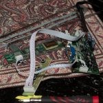
this is a close up of the circuit boards I ordered from a chinese supplier, she was lovely and helped me pick out the exact board to get my old laptop screen to work right away. I did test it, and it worked beautifully.
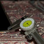
Taking some careful measurements. The boarder is about 1/4″, so that’s the size I’ll need to route in the frame in order to hold it securely. Precise measurements are required to get a professional, flush, and finished appearance. In this respect I am most definitely my father’s son.
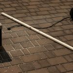
I routered the entire piece, and then I went at it with a chop saw for some very carefully measured angle cuts.
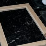
The frame is mostly pieced together (this is unsanded, and not glued or anything. Just to double check I didn’t screw the pooch royally in my cuts)
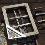
Sanded the edges and front face (lightly) with 80 grit to even things out, and get a good surface for the glue
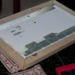
Post glue. Look at that flushness. I do say I’m impressed my own self.
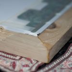
Seriously. LOOK AT THAT FLUSHNESS. MMmmmmm. I can taste the upvotes already. or not 🙁
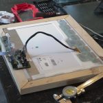
test fit with everything connected. Looking good so far.
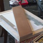
This will be the back brace (i skipped the cutting and stuff, kind of boring) it will give it a real naked back look. I hope it doesn’t look bad.
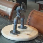
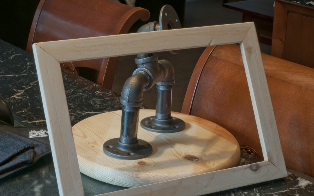
If you saw the last post, you’ll recognize this. This is going to be the mount, and it’s on the piece of wood that will be the base plate (so it doesn’t tip)
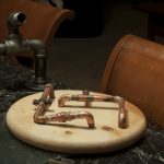
Here’s a tease of the copper accents almost finished. They’re all actually soldered together. I also took a blowtorch to them and quenched them randomly to get a really raw, grungy look. I’m happy with it so far.
I just finished painting and assembling some other pieces parts. More updates to come soon!

